LEGO 42102-B Mini CLAAS XERION Harvester 

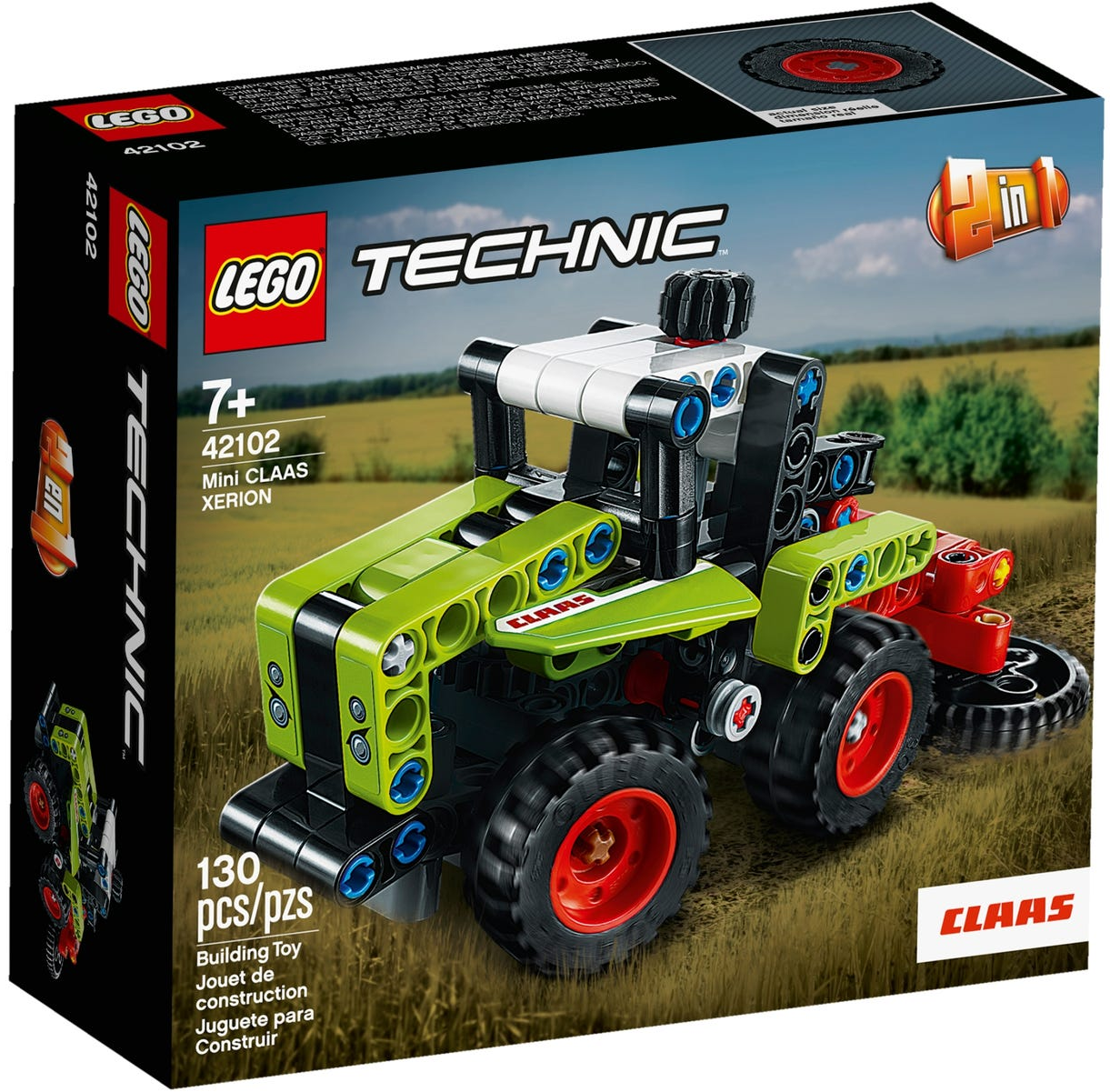
LEGO Audio & Braille Building Instructions for LEGO Technic set "Mini CLAAS XERION harvester".

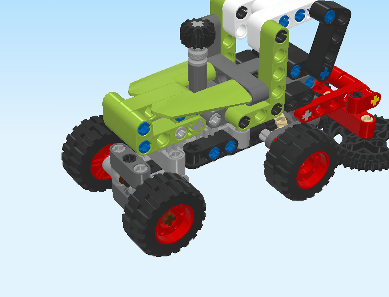
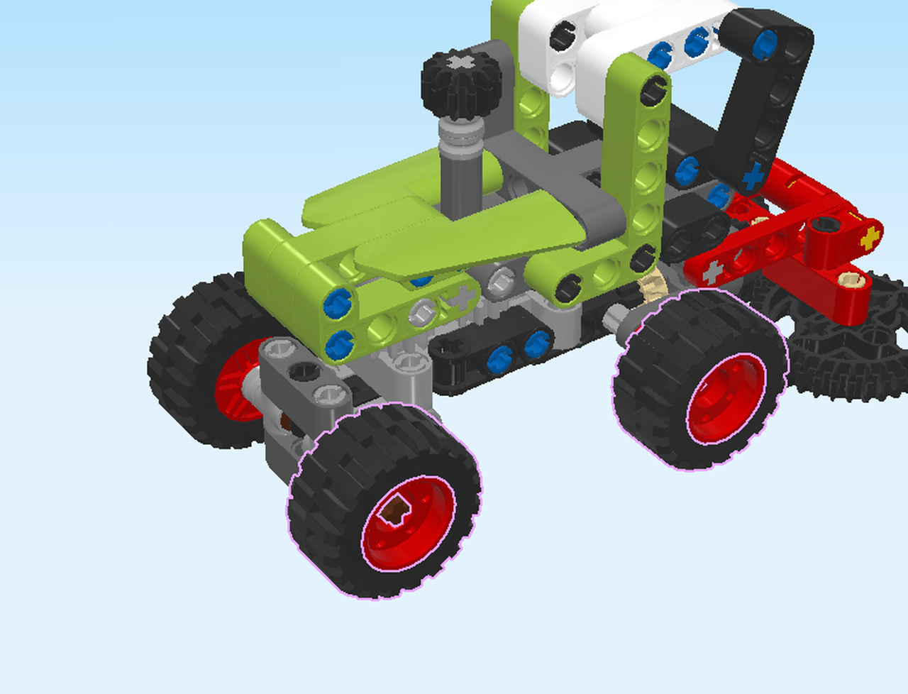
Build your very own LEGO version of a harvester machine from world-famous tractor maker CLAAS! It features the iconic green, red and gray color scheme just like the real CLAAS XERION machines.

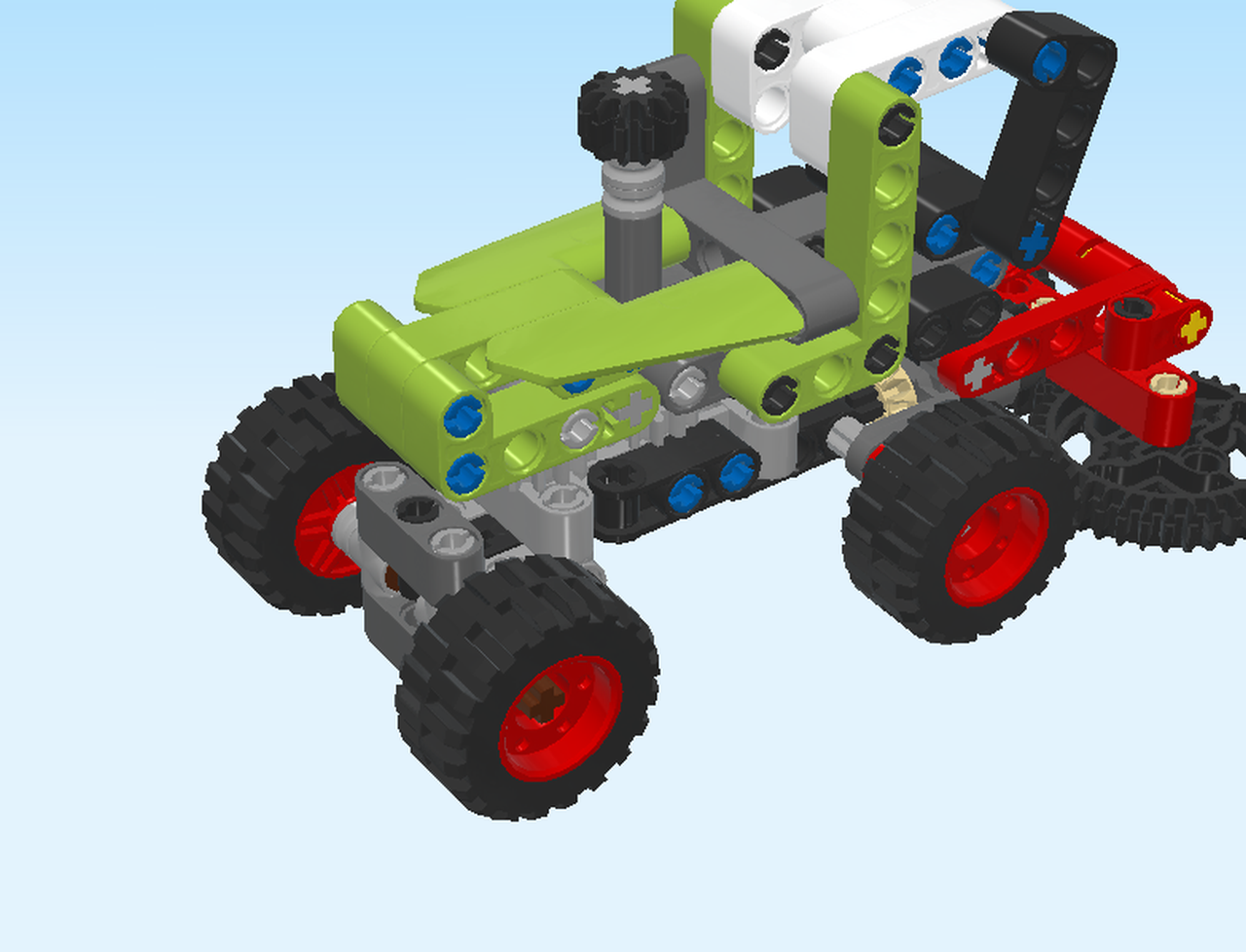
It is harvest time and your wheat crops are ready to be cut and brought home! The CLAAS XERION harvester with its flexible steering and rotary cutters at the back is the perfect machine for this job. Insiders' tip: this LEGO Technic set is a neat 2-in-1 package: alternatively, you can also build the CLAAS XERION tractor with it!

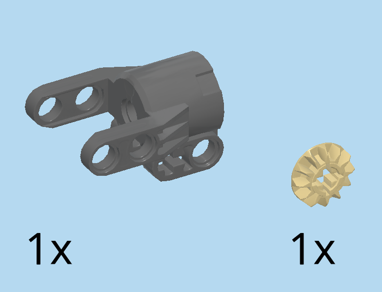
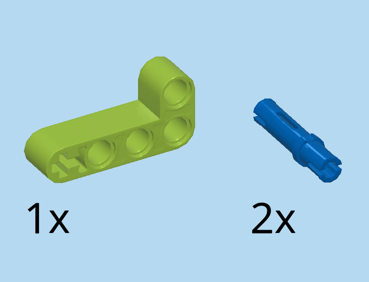
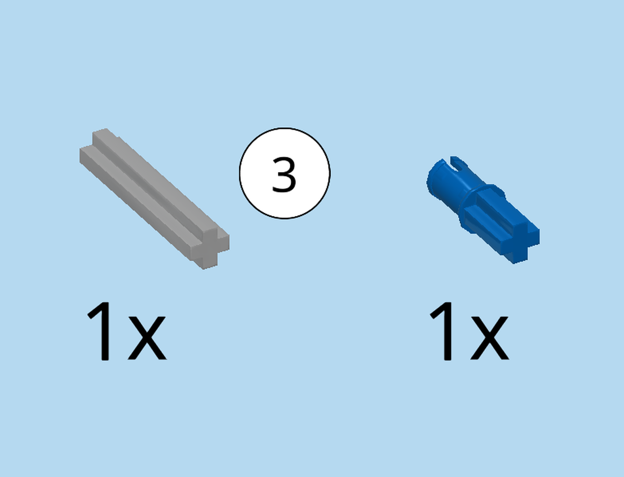
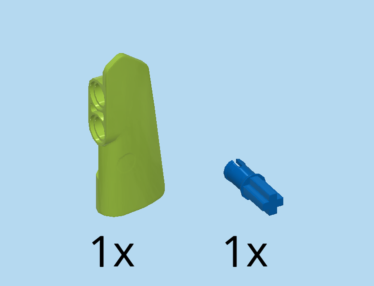
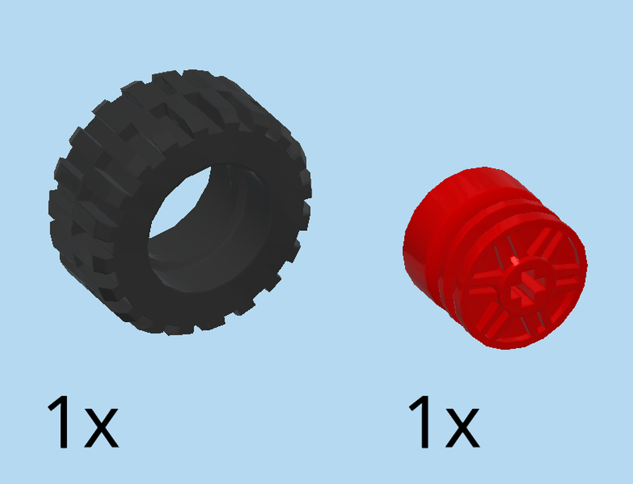
If you haven't built anything with this set yet, open the box. It contains a booklet with visual building instructions, a large and a small plastic bag as well as a sticker sheet with four stickers. Open both plastic bags carefully.

If you have built the tractor before, take everything apart.

Before you get started, ask a sighted person to help you sort the bricks by color. This way, you will be even faster in finding the correct pieces!

The harvester consists of a lot of smaller sub-builds and parts, but generally speaking it is one major build. You can still jump through sections though. Let's get started!

Collect the following 2 pieces:

1 black cross axle 4m,

and 1 black double conical wheel with 12 teeth 1m.

Put the wheel on the table.

Insert the cross axle from the top to the bottom until it is flush with the double conical wheel.

Find 1 bright red cross bushing 1x1.

Put it on top, dented end to the bottom.

Collect the following 2 pieces:

1 dark stone grey axle and pin connector block 3x4x2,

and 1 pale ocher yellow gear wheel with 12 teeth. This is the smaller one of the two pale ocher yellow gear wheels.

Place the axle and pin connector block on the table. Make sure the longer side rails of this piece are pointing to the left, and the shorter side rails are at the top.

Insert the cross axle from the right into the axle and pin connector block, double conical wheel to the right. The cross axle protrudes in the same direction as the longer side rails.

Now, push the gear wheel with 12 teeth left-to-right onto the other end of the cross axle, teeth to the left. Push it all the way to the stop position.

Great job! Make sure that the cross axle only protrudes on the left side. On the right side, it has to be flush with the double conical wheel. Make sure all pieces fit tightly together.

In general, make sure that you always keep the orientation of the structure, even if you put it aside for a moment. Remember: the longer side rails are pointing to the left, the shorter side rails are at the top.

Collect the following 2 pieces:

1 medium stone grey cross axle 7m,

and 1 bright red cross bushing 1x1.

Hold the cross axle horizontally.

Push the cross bushing on the left end of the cross axle, dented end to the right. The cross axle has to protrude approximately one centimeter on the left side.

Find 1 pale ocher yellow bevel gear with 20 teeth.

Mounting the cross axle and the bevel gear is a bit tricky so make sure to take your time. Remember: if we say "front" we are referring to the side of the structure that is facing you. This means that a "back-to-front" movement is a movement towards you. But for now, let's find the connection hole on the structure.

Find the longer side rail at the back of the axle and pin connector block. Identify its leftmost hole.

Then, insert in the shorter protrusion of the cross axle back-to-front into this hole. The cross axle should protrude a little bit towards the front, but not all the way to the next hole just yet.

Now, we will put the bevel gear onto this small protrusion of the cross axle: slide it in front of the longer side rail at the back, teeth to the front, so that it engages with the gear wheel on the right. You might have to pull back the cross axle a bit.

Now, make sure the cross axle engages with the bevel gear. Let it protrude a little to the front, but still not all the way to the front hole.

Great job so far! If all is done correctly, you will be able to twist the cross axle and all gear wheels will rotate.

Find 1 black technic beam 3m with offset cross hole.

It will also be mounted on the cross axle: hold it horizontally, cross hole to the left and running from top to bottom.

Put the rightmost round hole on the cross axle bit protruding to the front. To do so, insert the technic beam 3m from the left and push the cross axle from the back to the front until it engages. Now, you can push it further through the hole at the front.

Collect the following 2 pieces:

1 bright red cross bushing 1x1,

and 1 medium stone grey cross axle 3m.

First, put the cross bushing 1x1 on the structure: put it on the already mounted cross axle protruding at the front, dented end to the back.

Make sure that this cross axle is protruding symmetrically to the back and to the front.

Now, insert the cross axle 3m back-to-front into the cross hole on top of the structure at the back. Make sure it is flush with this hole. This cross axle now only protrudes to the back, so away from you.

Find 1 black angular technic beam 2m x 4m with cross hole 90°.

Hold the technic beam horizontally so that the longer end is on the right and pointing to the bottom. The shorter end is pointing to the left.

Insert the bottom tip of the longer beam between the two cross holes on top of the structure. Then push the cross axle all the way from the back to the front, overhanging symmetrically to the back and front.

Next, we will build sub-build 1.

Collect the following 2 pieces:

1 bright yellow cross axle 5m,

and 1 bright red technic beam 2m with offset cross hole.

Put the cross hole of the technic beam 2m on the left end of the cross axle, round hole overhanging to the front. Make sure the cross axle is flush with the cross hole.

Find 1 bright red technic lever 5m.

Hold it vertically and put its backmost cross hole right-to-left on the cross axle, technic lever overhanging to the front. Push it all the way to the technic beam 2m.

Now, mount sub-build 1: the frontmost cross hole of sub-build 1 connects with the shorter cross axle protruding to the back of the structure. Make sure the long cross axle of sub-build 1 protrudes to the front on the right side.

This also means that the technic beam 2m with offset cross hole is at the very back of the structure, and its empty round hole is to the left.

Great job so far! The beginning is often the hardest part, but you have already built a great basis by now! Remember to pay great attention to the orientation of the structure.

Find 1 bright red tube 2m with middle slot.

Put it on the cross axle protruding to the front on the right side.

Find 1 bright red technic lever 5m.

Hold it horizontally. Then, put its rightmost hole front-to-back on the cross axle on the right side, technic lever pointing to the left.

On its leftmost end, the technic lever connects with the very short cross axle protruding to the front in the middle of the structure.

Find 1 bright red technic beam 2m with offset cross hole.

Put its cross hole on the cross axle on the right edge, empty round hole to the left, and running from top to bottom.

Next, we will build sub-build 2.

Collect the following 4 pieces:

3 pale ocher yellow connector pegs 2m with cross axle pin,

and 1 bright red technic beam 7m.

Put the technic beam horizontally on the table, holes running top-to-bottom.

Insert one connector peg each into the leftmost, rightmost, and middle hole.

Collect the following 3 pieces:

2 black double conical wheels with 36 teeth,

and 1 black double conical wheel with 12 teeth 1m.

Put the double conical wheel with 12 teeth 1m on the middle cross axle pin.

Put the two double conical wheels with 36 teeth on the left and right cross axle pins. Use the middle holes of the wheels.

All three wheels will now engage.

Find 2 black connector pegs with middle friction ring.

Flip the part upside down.

Insert the 2 connector pegs into the second hole from the right and the second hole from the left.

Now, it is time to mount sub-build 2: put it vertically, connectors to the top. Find the 2 top-to-bottom holes on the right side of the structure. Insert sub-build 2 underneath on the right side, and connect the holes from the top with the connectors of sub-build 2.

If you turn the cross axle on the left side, all wheels should turn now. Well done!

Find 1 medium stone grey cross axle 3m.

Insert it top-to-bottom into the cross hole of the technic beam 3m hanging on the left side of the structure. Make sure the cross axle is flush with the hole and protrudes to the top.

Next, we will build sub-build 3. This sub-build consists of several smaller builds that we will call "parts ". Always make sure to maintain the building orientation of the different parts! In general, we will be building at 90° angles unless told otherwise.

Collect the following 3 pieces:

1 medium stone grey technic beam 3m with 2 top and 2 bottom connectors,

1 reddish brown cross axle 3m with end stop,

and 1 medium stone grey cross bushing 1x½.

Hold the technic beam 3m horizontally so that the connectors are pointing to the top and to the bottom.

Insert the cross axle 3m with end stop front-to-back into the leftmost hole, end stop to the front.

Put the cross bushing on the cross axle from the back. Push it all the way to the technic beam.

Find 2 dark stone grey technic beams 3m.

Put them vertically next to each other on the table, holes running top to bottom.

Now, insert the bottom connectors of sub-build 3 into the backmost holes of the two technic beams 3m.

Make sure the 2 technic beams 3m remain parallel and point to the front. The cross axle is pointing to the back.

Next, we will build part 3a.

Collect the following 3 pieces:

1 medium stone grey technic beam 3m with 2 top and 2 bottom connectors,

1 reddish brown cross axle 3m with end stop,

and 1 medium stone grey cross bushing 1x½.

Hold the technic beam 3m horizontally so that the connectors are pointing to the top and to the bottom.

Now, insert the cross axle back-to-front into the leftmost hole, end stop to the back.

Put the cross bushing on the cross axle from the front. Push it all the way to the technic beam.

Now, mount part 3a on sub-build 3. Careful: the 2 technic beams 3m at the bottom are not very stable.

Insert the two bottom connectors of part 3a into the frontmost holes of sub-build 3, cross axle pointing to the front.

If done correctly, there are now two cross axles pointing to the front and back on the left side. You probably noticed that the whole sub-build is flexibly moving. It will stay this way until the very end, because this is the suspension of the harvester. The rest of the structure, however, will become more stable as you are building.

Next, we will build part 3b.

Collect the following 2 pieces:

1 black knuckle arm 3m with connector and crank,

and 1 dark stone grey technic beam 3m.

Hold the knuckle arm horizontally, connector pointing to the top on the left, and crank pointing to the bottom on the right.

Put the technic beam 3m vertically on the connector of the knuckle arm. Use the middle hole. The two pieces form a 90° angle.

Now, mount part 3b on sub-build 3. First, find the two top connectors on the left side of the structure. Insert them into the 2 remaining holes of the technic beam 3m of part 3b. The knuckle arm fits into the slot running left-to-right in the middle of the structure.

Now, we will build part 3c.

Collect the following 3 pieces:

1 medium stone grey i-shaped technic beam 3m x 5m,

and 2 bright blue connectors 3m with asymmetric friction ring.

Hold the i-shaped technic beam 3m x 5m horizontally so that it is flat. This means that its shorter ends are pointing to the front and back.

The i-shaped technic beam has three front-to-back holes in the middle. Identify the right and the middle hole.

Insert the longer ends of the 2 connectors back-to-front into said holes.

Find 2 black technic beams 3m with offset cross hole.

Hold 1 horizontally, cross hole on the left side and running top to bottom.

Put its two round holes on the 2 connectors at the front.

Repeat symmetrically at the back.

Now, it is time to mount part 3c: put its leftmost top-to-bottom holes on the 2 connectors on the right side of sub-build 3. This means that part 3c is overhanging to the right at a 90° angle.

Next, we will build part 3d.

Collect the following 2 pieces:

1 medium stone grey cross axle 3m,

and 1 medium stone grey gear wheel with 16 teeth.

Put the gear wheel on the table.

Insert the cross axle from the top until it is flush with the cross hole.

Collect the following 2 pieces:

1 dark stone grey cross axle extension 2m,

and 1 medium stone grey technic beam 3m with 2 top and 2 bottom connectors.

Hold the technic beam 3m with top and bottom connectors horizontally, but make sure the connectors are pointing to the front and back now.

Put its right hole on the cross axle.

Put the cross axle extension on top.

Collect the following 2 pieces:

1 dark stone grey cross axle 4m with end stop,

and 1 medium stone grey gear wheel with 16 teeth.

Insert the cross axle 4m top-to-bottom into the left hole of the technic beam 3m, end stop to the top.

Mount the gear wheel from the bottom and push it all the way up. You might have to push down on the end stop of the cross axle for a tight fit.

Now, we will mount part 3d on sub-build 3. But first make sure that sub-build 3 is in the correct orientation: its cross axles are on the left side, pointing to the front and back. Swipe for the connection hole on sub-build 3.

On the top surface of sub-build 3 there are 3 beams 3m running front-to-back. The middle hole of the middle beam 3m will be the point of connection.

Take part 3d and insert its cross axle top-to-bottom into the middle hole of the middle beam on sub-build 3. Push down on its end stop until it fully engages. Part 3d is overhanging to the right.

That was quite complicated! Great job so far!

Now, sub-build 3 is finished and ready to be mounted on the structure. First, check the orientation of the structure: the large wheels are on the right side and at the bottom. On the left side, a cross axle is pointing to the top.

This cross axle is the point of connection of the structure. Now let's find its corresponding hole on sub-build 3.

Identify the middle hole of the rightmost beam running from back to front on sub-build 3.

Insert said cross axle of the structure bottom-to-top into this hole. Sub-build 3 is on the left side, and the rest of the structure on the right side.

You're making great progress Keep it up!

Find 1 black angled bushing 1x1 with cross hole 1m.

Put its cross hole top-to-bottom onto the cross axle pointing to the top in the middle of the whole structure. Make sure the round hole at the top is running front to back.

Find 2 bright blue connectors 3m with asymmetric friction ring.

Take one and insert its longer end front-to-back into the previous piece.

Identify the angled cross beam 2m x 4m to the right. Find its second hole from the top.

Insert the longer end of the other connector front-to-back into that hole.

Find 1 dark stone grey technic beam 7m.

Mounting this piece takes might be a bit tricky. Take your time and ask for help if needed!

Hold it horizontally, holes running front to back. Identify its rightmost and leftmost holes, and the third hole from the left. They will connect with three connectors at the front of the structure.

The rightmost hole of the beam connects with the previous piece on the right. The other 2 holes connect with 2 connectors to the left.

Find 1 dark stone grey technic beam 7m.

Mount it symmetrically at the back: hold it horizontally, holes running front to back. Put it on the three connectors pointing to the back, but make sure to leave out the fourth connector on the left.

Next, we will build 2 identical sub-builds 4.

Collect the following 6 pieces:

4 black connector pegs with middle friction ring,

and 2 black technic beams 2m.

Hold one technic beam 2m horizontally, holes running front to back.

Insert two connector pegs from the back.

Repeat to make a second part like this.

Now, you can mount the sub-builds 4: First, identify the technic beam 7m running left to right at the front of the structure. Find its second and third hole from the right.

Insert the connectors of one of the two sub-builds front-to-back into these holes.

Repeat symmetrically at the back.

Now, let's build sub-build 5.

Collect the following 2 pieces:

1 bright blue connector 3m with asymmetric friction ring,

and 1 black technic beam 2m.

Hold the technic beam 2m horizontally, holes running front to back.

Insert the shorter end of the connector back-to-front into the left hole.

Now, mount sub-build 5: First, find the 2 holes at the very top in the right half of the structure. Insert the connector of sub-build 5 front-to-back into the left hole.

Find 1 black technic beam 2m.

Put it horizontally back-to-front on the connector you have just mounted. Insert that connector into the left hole.

Next up is sub-build 6.

Collect the following 3 pieces:

1 bright yellowish green angular technic beam 2m x 4m with cross hole 90°,

and 2 bright blue connectors 3m with asymmetric friction ring.

Put the angular technic beam flat on the table, shorter beam on the left and pointing to the back.

Insert the shorter ends of the connectors into the two leftmost holes. These are the holes of the shorter beam.

Now, let's make part 6a.

Collect the following 2 pieces:

1 bright yellowish green angular technic beam 2m x 4m with cross hole 90°,

and 1 bright blue connector 3m with asymmetric friction ring.

Hold the angular technic beam horizontally so that it is flat. Make sure the shorter beam is on the left side, this time pointing to the front.

Find the second hole from the right. Insert the longer end of the connector bottom-to-top into this hole.

Now, mount part 6a in this orientation: insert the 2 connectors of sub-build 6 on the left side bottom-to-top into the leftmost holes of part 6a.

Collect the following 2 pieces:

1 bright blue connector peg 2m with cross axle pin,

and 1 medium stone grey cross axle 3m.

Insert the cross axle pin of the connector peg 2m bottom to top into the rightmost cross hole at the back.

Insert the cross axle 3m into the rightmost hole at the front.

Well done! Now it's time to mount sub-build 6: flip it 90° to the front so that the 4 connectors and 1 cross axle are pointing at you.

Sub-build 6 will be mounted from the back. It has 2 points of connection and they are a bit tricky to find. Listen carefully!

First, connection point A: identify the cross axle pointing to the front at the bottom of sub-build 6.

To the left of that cross axle, there is a round hole. This is the hole of connection point B.

Let's find connection point A on the structure now: First, find the cross axle extension pointing to the top. To its left, there is a front-to-back hole. This hole will later connect with the cross axle of sub-build 6. Now, swipe for connection point B.

To the left of that hole, there is a connector pointing to the back. It will connect with the connecting hole of sub-build 6.

Now, mount sub-build 6 carefully from the back, connecting said holes, connectors and axles. Make sure it clicks for a tight fit.

Find 1 bright yellowish green angular technic beam 2m x 4m with cross hole 90°.

Hold it horizontally, shorter beam on the left side, and pointing to the top.

Mount it in this orientation at the front on the left, just like the sub-build you have just mounted at the back. It will connect with 2 connectors and 2 cross axles protruding to the front.

Well done! Making sure that all holes and connectors fit is a tricky job sometimes, isn't it?

Next, we will build sub-build 7, the mudguard of the harvester.

Collect the following 2 pieces:

1 bright yellowish green left mudguard panel 2x5,

and 1 bright blue connector peg 2m with cross axle pin.

Hold the left mudguard panel horizontally, arrow tip to the left, 2 round holes to the back and at the bottom. If this does not add up, you might have the right instead of the left mudguard panel.

Insert the cross axle pin into the cross hole on the right side.

Now, you can mount sub-build 7: find the 2 connectors pointing to the front at the top of the structure.

Mount sub-build 7 from the front by inserting those connectors into the 2 round holes at the back of sub-build 7.

Now, we will repeat this at the back: let's build sub-build 8.

Collect the following 2 pieces:

1 bright yellowish green right mudguard panel 2x5,

and 1 bright blue connector peg 2m with cross axle pin.

Hold the right mudguard panel horizontally, arrow tip to the left, 2 holes to the front and at the bottom.

Insert the cross axle pin into the cross hole on the right side.

Now, you can mount sub-build 8: put the left hole at the front on the connector pointing to the back at the top of the structure.

Find 1 dark stone grey angular technic beam 3m x 5m 90°.

Hold it vertically, shorter beam at the back and pointing to the top. Find the second hole from the front and the fourth hole from the front.

Now, identify the 2 connectors pointing to the right at the top and in the middle of the structure. Connect them with said holes.

Next, we will build sub-build 9.

Collect the following 4 pieces:

3 black connector pegs with middle friction ring,

and 1 bright yellowish green angular technic beam 3m x 5m 90°.

Hold the angular technic beam vertically, longer beam at the back and pointing to the top.

Insert 1 connector peg left-to-right into the frontmost hole at the bottom.

Insert 1 connector peg left-to-right into the backmost hole at the bottom.

Insert the last connector peg left-to-right into the topmost hole.

Now, turn this sub-build 90° clockwise. This means that the connectors are now pointing to the back, and the longer beam is on the right side, pointing to the top. All set? Great! Now it's time to mount it!

First, find the angular technic beam running vertically at the top and in the middle of the structure. The hole just below that beam at the front is already filled. However, the 2 holes to its left and right are free. They are your points of connection.

Now, connect the 2 bottom connectors of sub-build 9 with said holes. Remember those connection holes for later because you will mount a similar sub-build in the same holes at the back.

Next, we will build sub-build 10, the drivers' cabin of the harvester.

Collect the following 3 pieces:

2 bright blue connectors 3m with asymmetric friction ring,

and 1 white technic beam 3m.

Hold the technic beam 3m horizontally, holes running front to back.

Insert the longer ends of the connectors front-to-back into the leftmost and middle holes.

Find 2 white angular technic beams 2m x 4m with cross hole 90°.

Hold one horizontally, shorter beam to the left and pointing to the bottom. Identify the second and third top hole from the left.

Connect said holes front-to-back with the 2 connectors at the front.

Repeat symmetrically at the back.

You can now feel a recess on the left side of the drivers' cabin. On the right side, all three beams are flush.

Find 2 bright blue connector pegs 2m with cross axle pin.

Insert the cross axle pins into the rightmost cross holes at the front and back.

Now, sub-build 10 is finished! It will be mounted from the back. Find the leftmost topmost hole on the front side of sub-build 10.

Now, identify the topmost connector on the structure pointing to the back. Insert it into said hole.

Make sure that the drivers' cabin is attached in straight 90° angles.

Next, we will build sub-build 11.

Collect the following 4 pieces:

1 bright yellowish green angular technic beam 3m x 5m 90°,

and 3 black connector pegs with middle friction ring.

Hold the angular technic beam horizontally, longer beam on the right and pointing to the top.

Insert 1 connector peg into the leftmost hole at the bottom.

Insert 1 connector peg into the rightmost hole at the bottom.

Insert the last connector peg into the topmost hole.

Now, we will mount sub-build 11 at the back of the structure - it will be part of the drivers' cabin and has 3 points of connection.

Just like at the front, the 2 bottom connectors of sub-build 11 will connect with the 2 holes below the angular technic beam in the middle of the structure.

The topmost connector of sub-build 11 connects with the topmost leftmost hole of the drivers' cabin at the back.

Great job! You're almost there!

Now we will build sub-build 12.

Collect the following 2 pieces:

1 bright blue connector peg 2m with cross axle pin,

and 1 black angular technic beam 2m x 4m with cross hole 90°.

Put the angular technic beam flat on the table horizontally, shorter beam on the right and pointing to the front.

Put the cross axle pin into the leftmost cross hole.

Next, we will mount sub-build 12 at the front of the structure. It is also part of the drivers' cabin and has 2 points of connection.

Careful: the angular technic beam will not be mounted in a 90° angle, but tilted a bit to the right. Swipe to hear the connection points.

Connection point A of sub-build 12 is the frontmost hole of the short beam. It will connect with the connector protruding to the front at the very top of the structure.

Now, connection point B: the connector peg on sub-build 12 will connect below on the structure: find the hole that is in a straight line below connection point A, but a bit more towards the center of the structure.

Connect said connectors and holes. You might have to move the top of the drivers' cabin a bit.

If done correctly, the corner of sub-build 12 is tilted a bit to the right.

Now, we will repeat this at the back of the structure: let's build sub-build 13.

Collect the following 2 pieces:

1 bright blue connector peg 2m with cross axle pin,

and 1 black angular technic beam 2m x 4m with cross hole 90°.

Put the angular technic beam flat on the table horizontally, shorter beam on the left side and pointing to the front.

Insert the cross axle pin into the rightmost cross hole.

Now, you can mount sub-build 13 at the back, symmetrically to sub-build 12. Find the 2 points of connection first.

The frontmost hole of sub-build 13 on the left side will connect with the topmost connector on the structure, pointing to the back.

The connector peg on sub-build 13 will again connect with the hole below connection point A.

Connect said connectors and holes.

Very well done! The drivers' cabin is finished now.

Next, we will build sub-build 14, the steering crank of the harvester.

Collect the following 2 pieces:

1 medium stone grey cross axle 3m,

and 1 black double conical wheel with 12 teeth 1m.

Put the double conical wheel on the table.

Insert the cross axle from the top.

Find 2 medium stone grey cross bushings 1x½.

 Put them both on top.

Now you can mount the steering crank: insert the cross axle into the cross axle extension pointing to the top in the left half of the structure.

Finally, we will assemble the 4 wheels.

Collect the following 8 pieces:

4 black wide rubber tires with profile,

and 4 bright red wide rims with cross hole.

Put the tires on the rims.

Now, mount the wheels on the four cross axles at the front and back sides of the structure, spokes facing inwards.

The CLAAS XERION harvester is finished! Great job! The rotary cutter at the bottom will cut down your wheat crops in no time, and thanks to the steering crank you can decide where the harvester goes next!

You will have plenty of spare parts left. Make sure to keep them! If you want to rebuild the harvester into the tractor, you will need most of those spare parts.

Enjoy!