LEGO 42102-A Mini CLAAS XERION Tractor 

LEGO Audio & Braille Building Instructions for LEGO Technic set "Mini CLAAS XERION tractor".

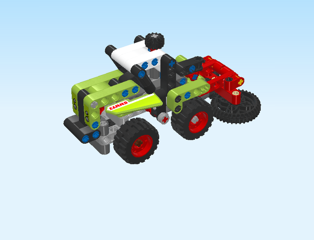
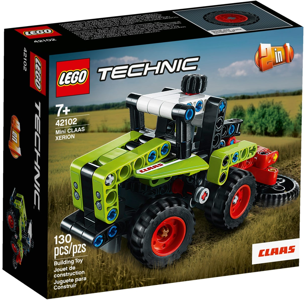
Build your very own LEGO version of a tractor from world-famous tractor maker CLAAS! It features the iconic green, red and gray color scheme just like the real CLAAS XERION tractor. This cool model has a working steering as well as a rotary cutter driven by the wheels. You can lift and lower the cutter, just like the real thing. Time to gather the harvest? No problem! With its 2-in-1 design, this model rebuilds into a harvester, so the fun goes on.

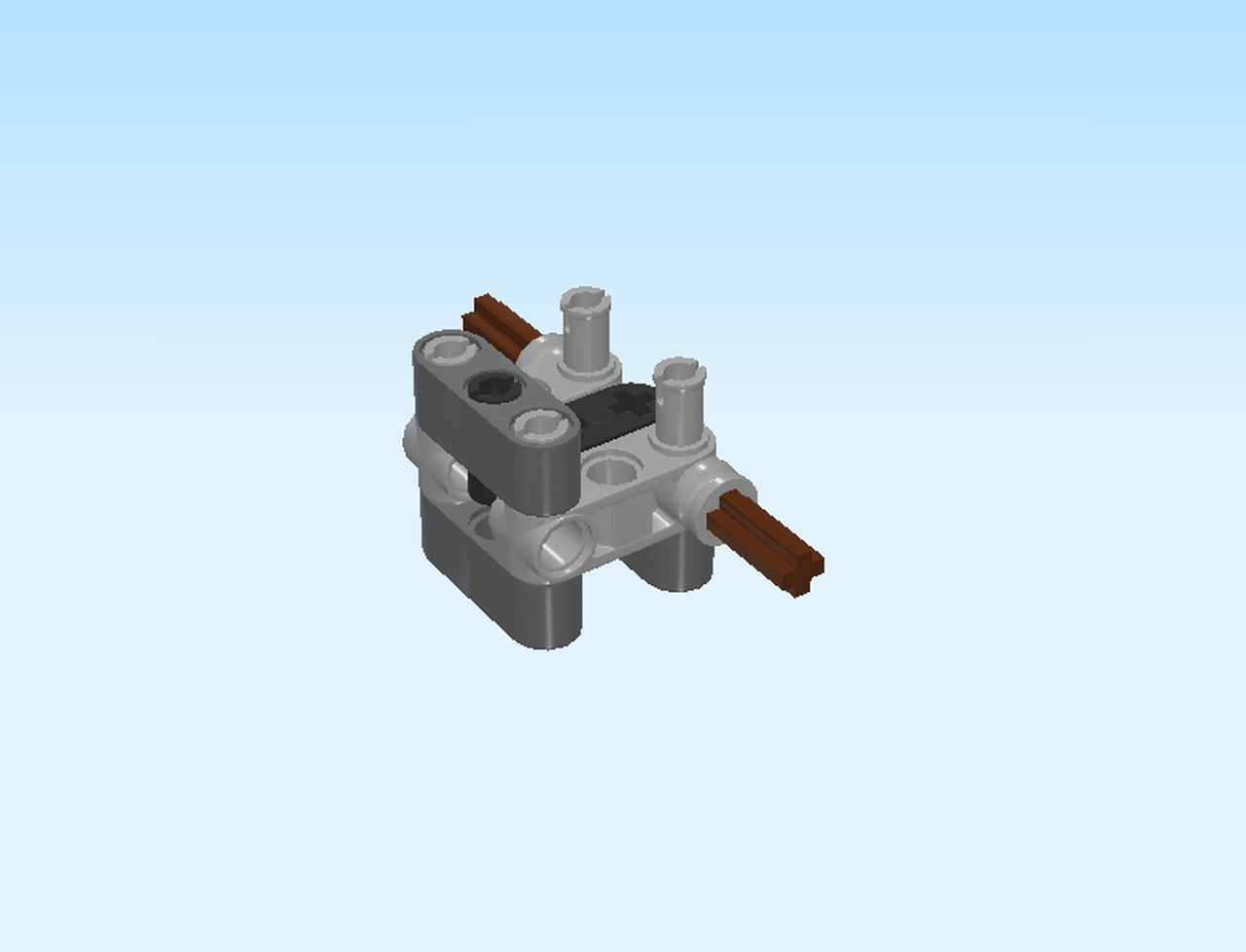
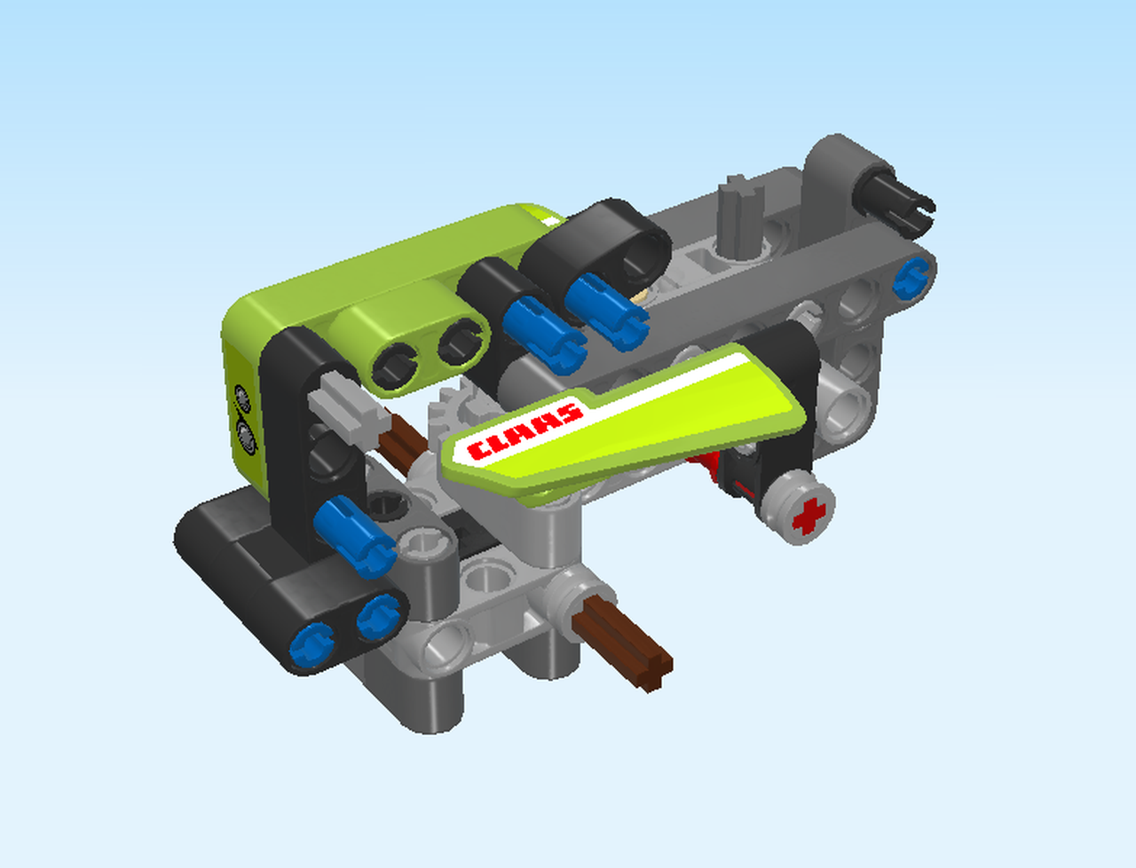
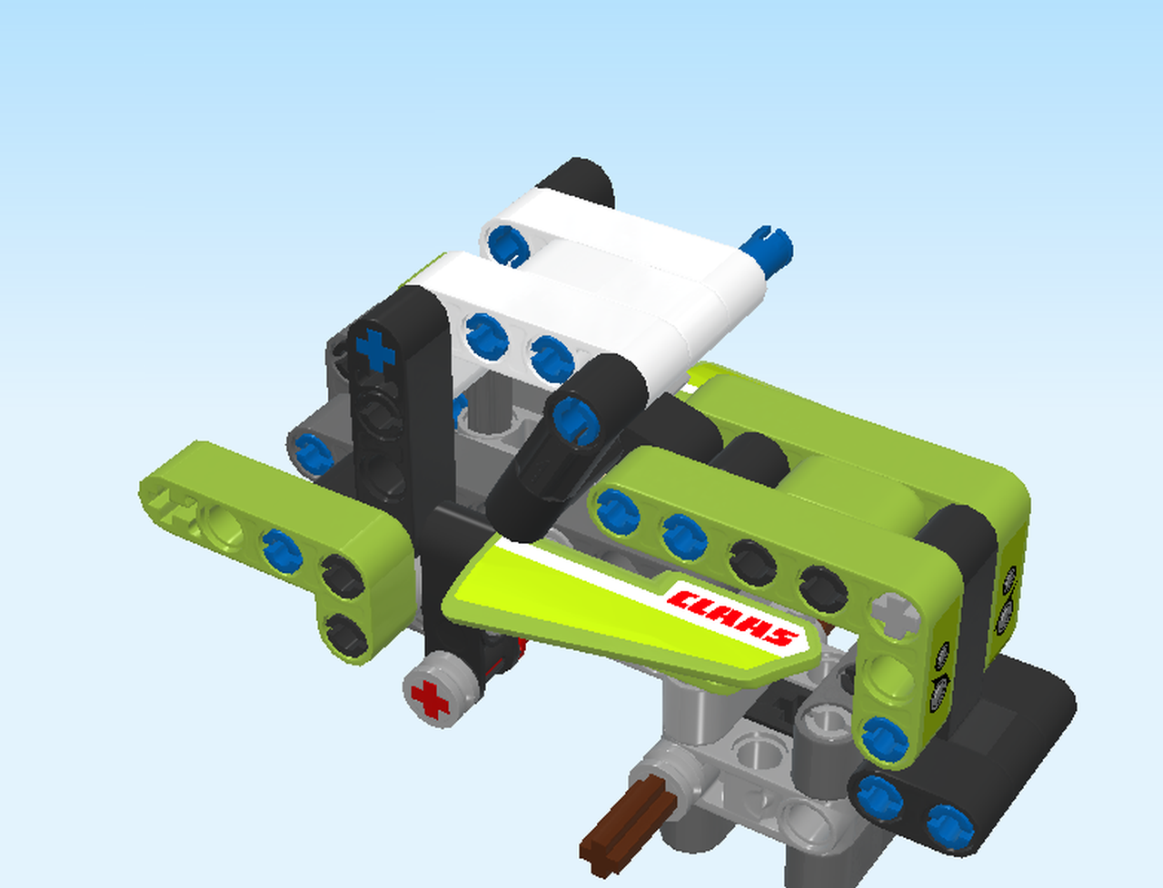
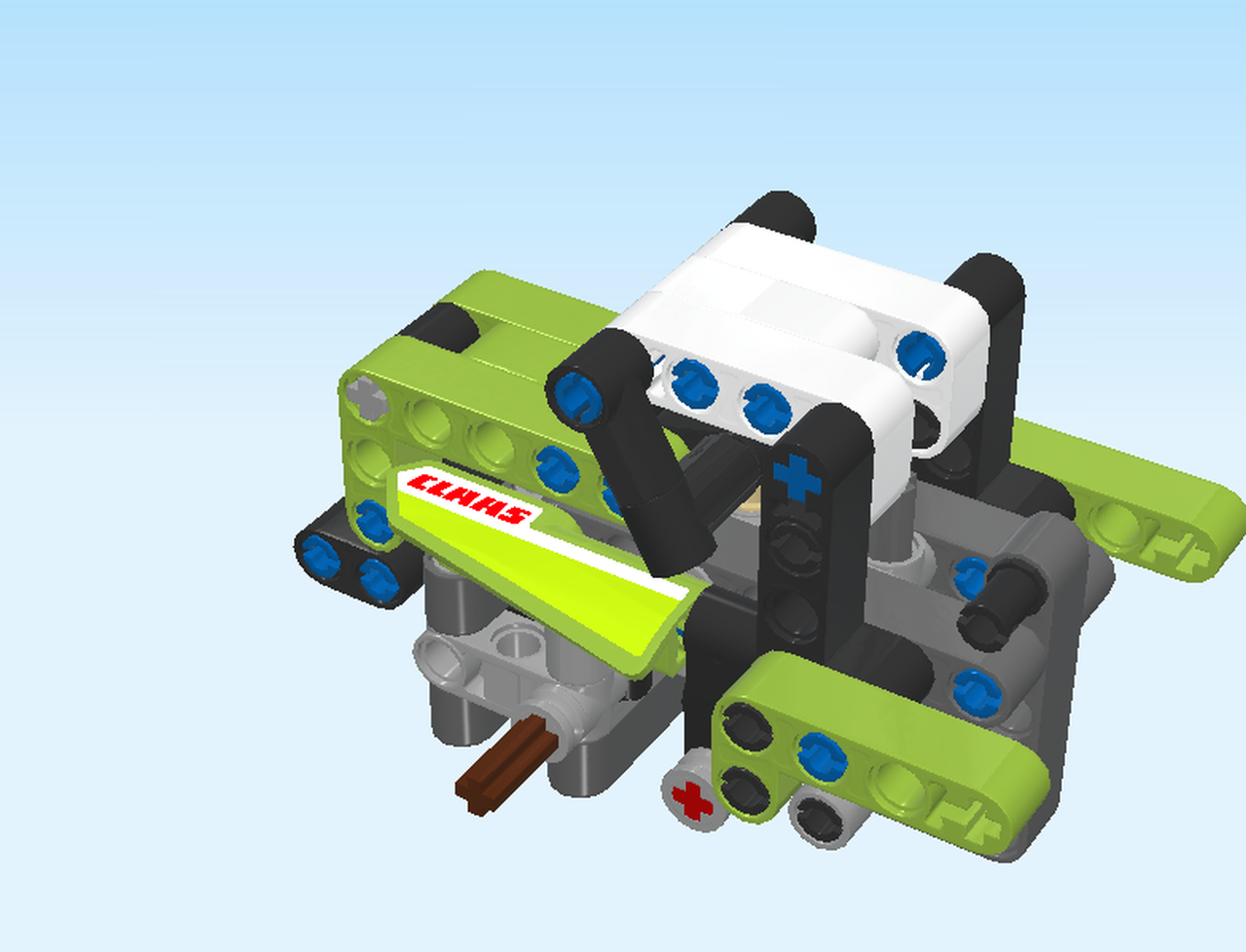
On the box cover, the tractor is shown from the front: it has cool headlights, big sturdy wheels, and on top of the cabin there is a drive crank that you can use for steering! The rotary cutters at the rear are cutting through a wheat field.

Open the box. This can be tricky; ask someone to help you!

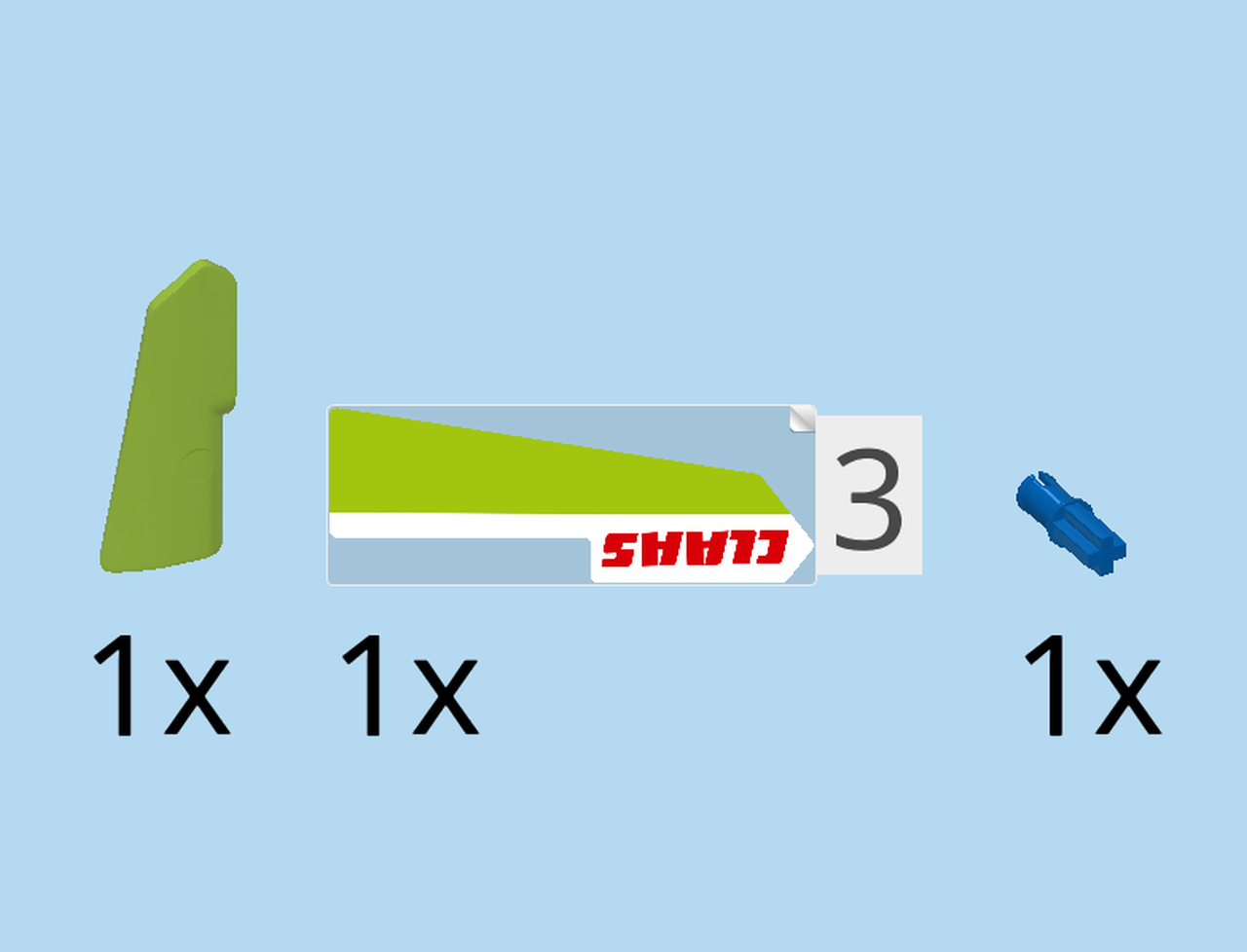
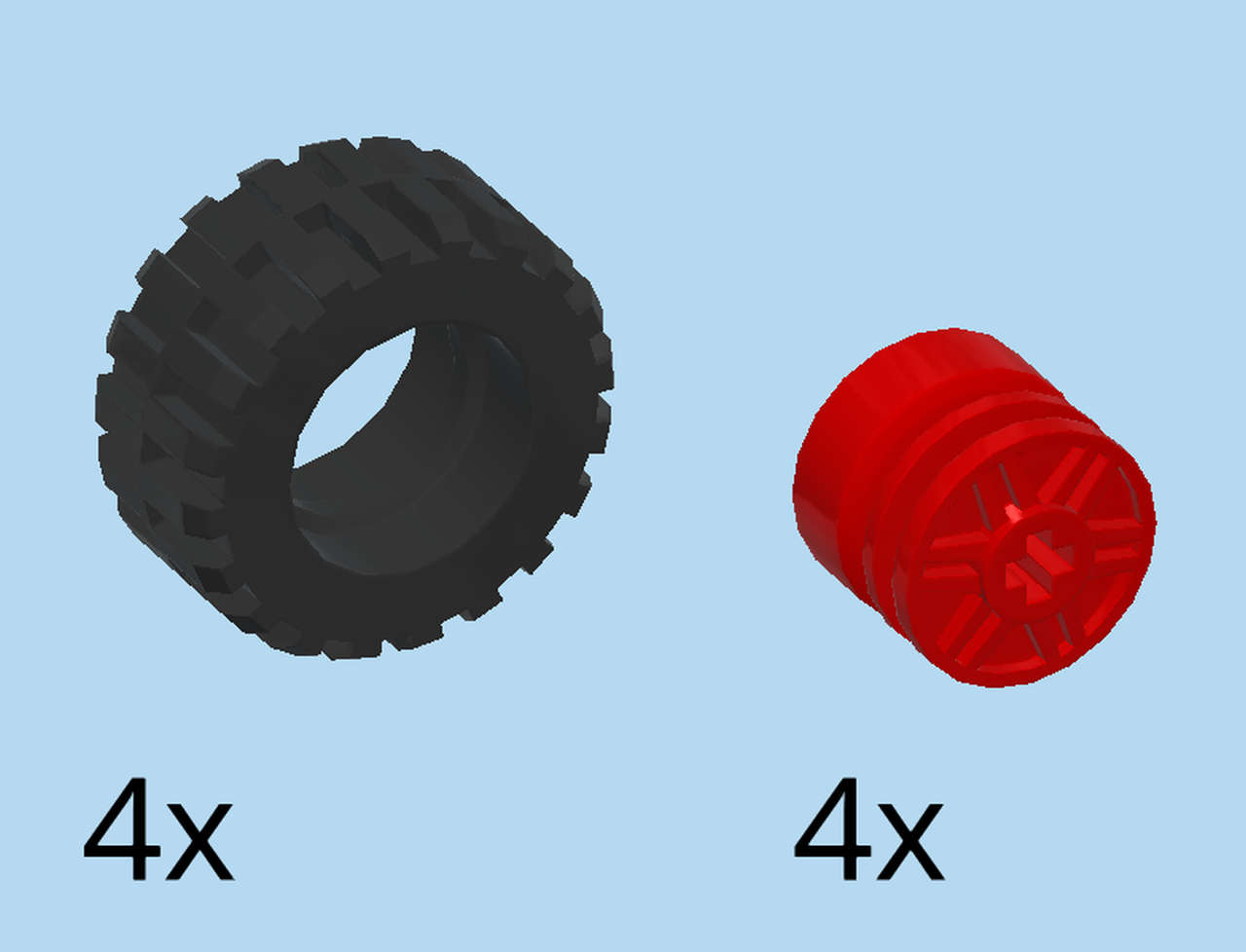
The box contains a booklet with visual building instructions, a large and a small plastic bag as well as a sticker sheet with four stickers.

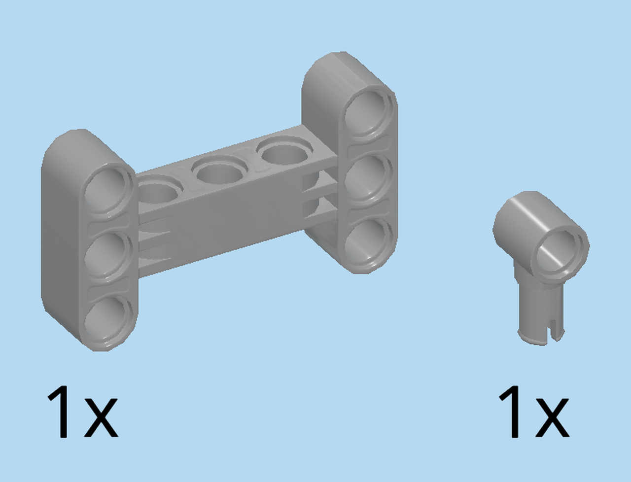
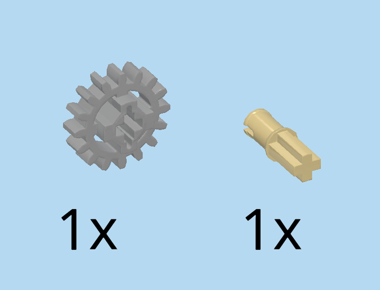
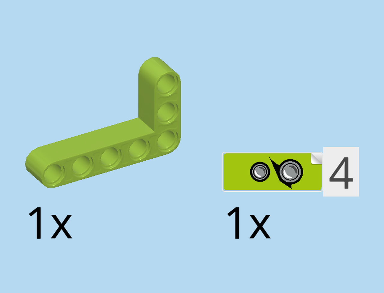
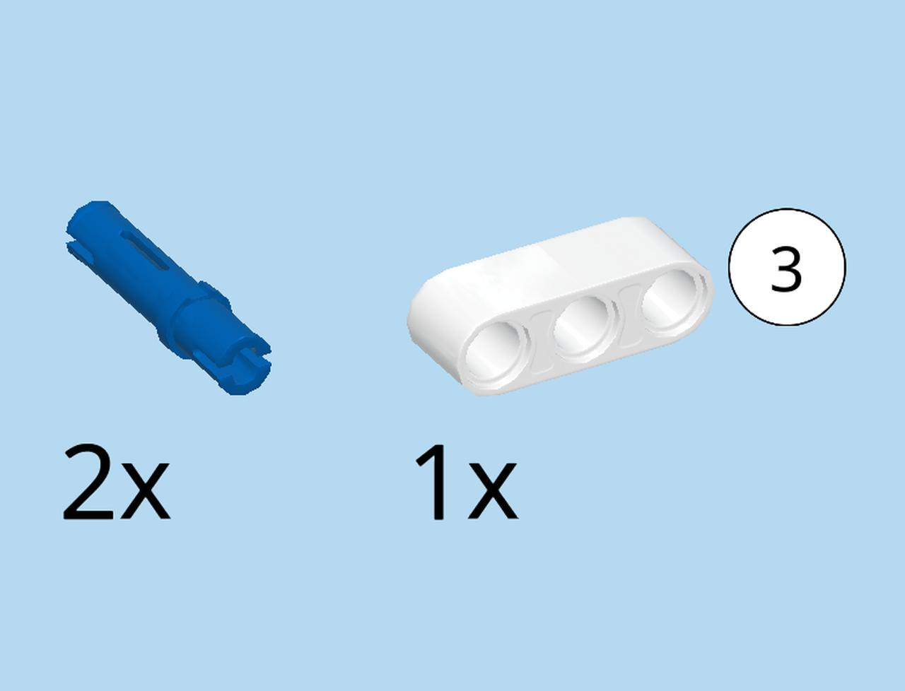
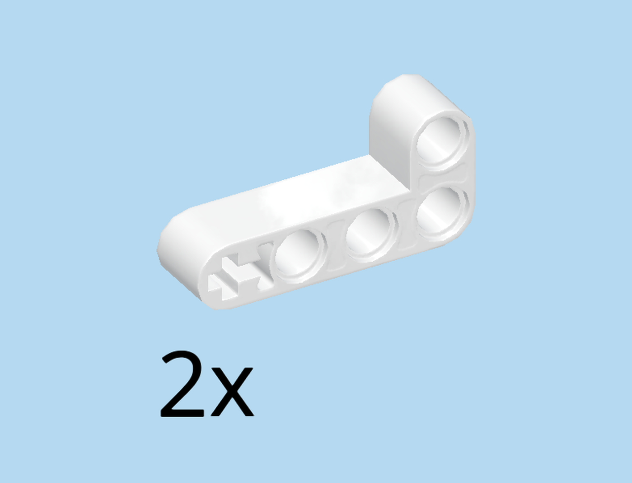
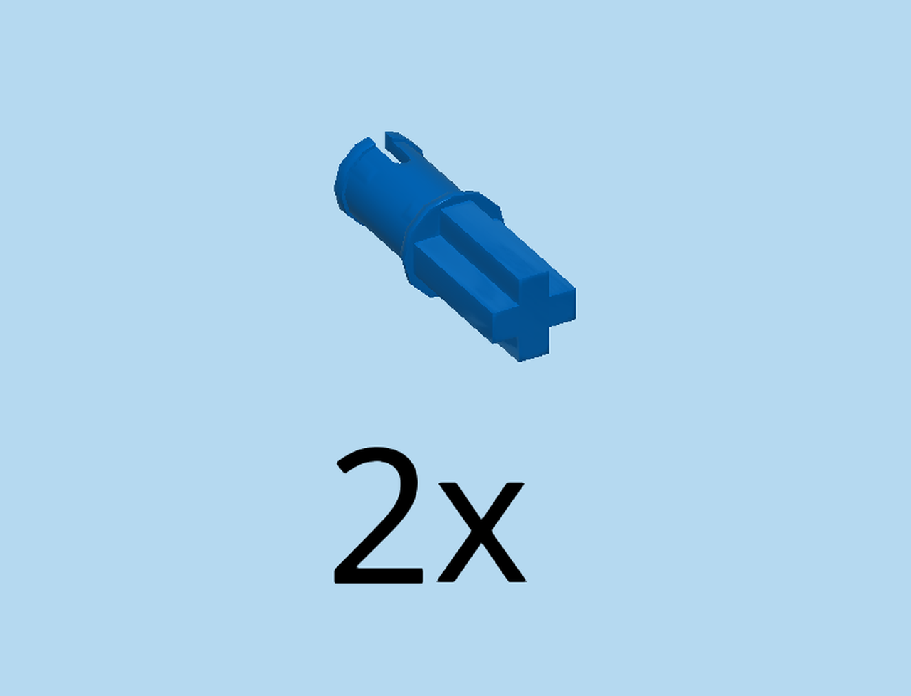
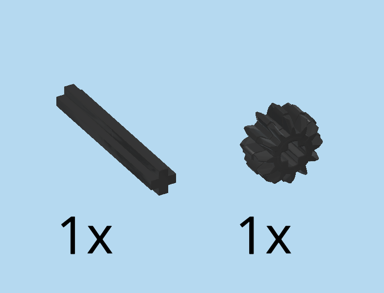
Open both plastic bags carefully. Before you get started, ask a sighted person to help you sort the bricks by color. This way, you will be even faster in finding the correct pieces!

The tractor consists of a lot of smaller sub-builds and parts, but generally speaking it is one major build. You can still jump through sections though. Let's get started!

Collect the following 3 pieces:

1 medium stone grey technic beam 3m with 2 top and 2 bottom connectors,

1 reddish brown cross axle 3m with end stop,

and 1 medium stone grey cross bushing 1x½.

Hold the beam horizontally so that the connectors are pointing to the top and to the bottom.

Insert the cross axle from the front to the back into the right hole, end stop to the front.

Put the cross bushing 1x½ on the cross axle from the back.

Remember: if way say "front", we are referring to the side of the structure that is facing you. So, for instance, a "back-to-front" movement therefore is a movement towards you. For the structure you have built so far this means that the cross axle is pointing away from you, and its end stop is located at the side that is facing you.

Find 2 dark stone grey technic beams 3m.

Put them vertically next to each other on the table, holes running top to bottom.

Insert the 2 bottom connectors into the backmost holes of the beams, cross axle pointing to the back.

The beams 3m will move quite freely. Make sure they are parallel to each other and keep protruding vertically to the front.

Next, we will build sub-build 1.

Collect the following 3 pieces:

1 reddish brown cross axle 3m with end stop,

1 medium stone grey technic beam 3m with 2 top and 2 bottom connectors,

and 1 medium stone grey cross bushing 1x½.

Insert the cross axle back-to-front into the right hole of the beam.

Put the cross bushing 1x½ front-to-back on the cross axle.

Now, mount sub-build 1 on the structure: insert the bottom connectors of sub-build 1 into the frontmost holes, cross axle protruding to the front.

Great job so far! The structure is still quite flexible - or even unstable -, but don't worry: it will gain stability the more we build on it. Keeping the correct orientation, however, is crucial for all upcoming building steps. Even though these two technic beams will remain flexible until the very end, because they will be the suspension of the tractor, make sure that they remain at a 90° angle during building and always run front-to-back. All upcoming steps will require you to build at 90° angles unless we tell you otherwise explicitly.

Next, let's build sub-build 2.

Collect the following 2 pieces:

1 black knuckle arm 3m with connector and crank,

and 1 dark stone grey technic beam 3m.

Hold the knuckle arm horizontally, connector pointing to the top on the left, and crank pointing to the bottom on the right.

Put the technic beam 3m vertically on the connector of the previous piece. Use the middle hole. The two pieces form a 90° angle.

Now, mount sub-build 2 on the structure. This is quite tricky, so do ask for help if needed. Find the two top connectors on the left side of the structure. Insert them into the 2 remaining holes of the technic beam 3m of sub-build 2. The knuckle arm fits into the slot running left-to-right in the middle of the structure.

Up next is sub-build 3.

Collect the following 2 pieces:

1 medium stone grey bushing 1x1 with bottom connector,

and 1 medium stone grey i-shaped technic beam 3m x 5m.

Hold the i-shaped technic beam horizontally so that it is flat. This means that its shorter ends are pointing to the front and back.

Insert the connector of the bushing 1x1 bottom-to-top into the frontmost hole on the right edge. Make sure that the bushing hole at the bottom is running front-to-back.

Find 1 dark stone grey cross axle 4m with end stop.

Insert the cross axle 4m bottom-to-top into the middle hole on the right edge, end stop to the bottom. It will only be firmly connected after the next step.

Find 1 medium stone grey gear wheel with 16 teeth and cross hole.

Put it on the cross axle from the top. Push it all the way down, and make sure that the cross axle is pushed all the way up. Keep this orientation for mounting!

Now, mount sub-build 3: find the 2 top connectors on the left side of the structure. Insert them into the leftmost cross beam of sub-build 3. This means that sub-build 3 is overhanging to the right at a 90° angle.

Next, we will build sub-build 4.

Collect the following 2 pieces:

1 medium stone grey cross axle 3m,

and 1 medium stone grey gear wheel with 16 teeth and cross hole.

Insert the cross axle into the cross hole of the gear wheel. Push it until one end of the cross axle is flush with the hole.

Now, mount sub-build 4: in the left half at the top of the structure, there are two beams 3m running front to back. The middle hole of the right beam is your connection point. Insert the cross axle of sub-build 4 into this hole.

Great job! The first steps are often the hardest. You have already built a great basis by now! Remember to pay great attention to the orientation of the structure.

Next, let's build sub-build 5.

Collect the following 2 pieces:

1 dark stone grey angular technic beam 3m x 5m, 90°,

and 1 black connector peg with middle friction ring.

Hold the angular technic beam so that the longer beam is on the right and pointing to the top.

Insert the connector peg front-to-back into the leftmost hole of the shorter beam.

Now, mount sub-build 5: find the bushing 1x1 at the bottom on the right edge of the structure. Insert the connector of sub-build 5 back-to-front into this hole. Make sure the longer beam of sub-build 5 is now pointing to the top on the right side.

Collect the following 2 pieces:

1 bright blue connector 3m with asymmetric friction ring,

and 1 black connector peg with middle friction ring.

Insert the connector peg with middle friction ring front-to-back into the topmost hole at the right edge.

Insert the longer end of the connector 3m with asymmetric friction ring front-to-back into the hole below. But don't push it in all the way. It only needs to be flush at the back.

Next, we will build sub-build 6.

Collect the following 2 pieces:

1 dark stone grey technic beam 7m,

and 1 medium stone grey technic beam 3m with 2 top and 2 bottom connectors.

Hold the technic beam 7m horizontally, holes running front-to-back.

Insert two connectors of the technic beam 3m with top and bottom connectors in the middle, leaving 2 spare holes on each side. Make sure the piece is overhanging to the front, this means it is pointing towards you.

Collect the following 2 pieces:

1 medium stone grey gear wheel with 16 teeth and cross hole,

and 1 pale ocher yellow connector peg 2m with cross axle pin.

Insert the cross axle pin top-to-bottom into the gear wheel.

Now, insert the connector bottom-to-top into the left hole at the very front. It is the left hole of the technic beam 3m with top and bottom connectors.

Next up, we will make part 6a.

Collect the following 2 pieces:

1 bright blue connector 3m with asymmetric friction ring,

and 1 black technic beam 2m.

Put the technic beam 2m vertically on the table, holes to the top.

Insert the shorter end of the connector top-to-bottom into the backmost hole.

Insert the longer end of the connector front-to-back into the leftmost hole of sub-build 6. Make sure the technic beam 2m protrudes to the top.

Now, you can mount sub-build 6 on the structure. It has two points of connection. First, identify the right hole at the front of sub-build 6. It runs top to bottom.

Then, identify the cross axle in the middle of the right half of the structure. It runs top-to-bottom as well.

Put the hole top-to-bottom on the cross axle. The three gear wheels will engage now.

Next, find the second connector from the top at the right edge of the structure. Push it all the way to the back and make sure it engages with the rightmost hole of sub-build 6 which is now mounted at the back of the structure.

This was a complicated step! Well done!

Next, we will build sub-build 7.

Collect the following 2 pieces:

1 dark stone grey technic beam 7m,

and 1 black connector peg with middle friction ring.

Hold the technic beam 7m horizontally, holes running front-to-back.

Insert the connector peg front-to-back into the leftmost hole.

Now, mount sub-build 7 on the structure: find the second connector from the top at the right edge of the structure.

Put the rightmost hole of sub-build 7 front-to-back onto this connector. There are two more connectors to the left that will engage as well. On the left side, a connector will protrude to the front after mounting.

Next, we will build sub-build 8.

Collect the following 2 pieces:

1 medium stone grey cross bushing 1x½,

and 1 bright red cross axle 6m.

Put the bushing on one end of the cross axle.

Next, we will make part 8a.

Collect the following 2 pieces:

1 black technic beam 3m with offset cross hole,

and 1 medium stone grey bushing 1x1 with bottom connector.

Hold the technic beam upright vertically, cross hole at the bottom and running front to back.

Insert the connector of the bushing 1x1 right-to-left into the middle hole of the technic beam 3m. Make sure the bushing hole is running front to back now.

Now, insert the cross axle 6m back-to-front into the cross hole at the bottom, cross bushing 1x½ at the back.

Find 1 bright red cross bushing 1x1.

Put it front-to-back on the cross axle, dented end to the front. Make sure to push it until it touches the beam 3m.

Next, we will make part 8b, the front mudguard of the tractor.

Collect the following 3 pieces:

1 bright yellowish green right mudguard panel 2x5,

1 yellowish green CLAAS sticker number 1 for mudguard panel. You can also take care of the sticker later.

and 1 bright blue connector peg 2m with cross axle pin.

Hold the right mudguard panel horizontally, arrow tip to the left, 2 holes at the front and at the bottom. If this does not add up, you might have the left instead of the right mudguard panel.

You can decorate this piece with the sticker now, or skip the next 2 sentences and keep this step for later.

Attach CLAAS sticker number 1 according to the mudguard panel form.

The sticker is divided horizontally: one half is bright yellowish green - the characteristic CLAAS brand color - and the other half is white with the bright red CLAAS logo.

Insert the cross axle pin right-to-left into the cross hole on the right side.

Now, you can mount part 8b: insert the connector left-to-right into the topmost hole of sub-build 8. If done correctly, the mudguard is pointing to the left, and the cross axle at the bottom is pointing to the front. Keep this orientation for the next step!

Now, you can mount sub-build 8. It will be attached at the back on the left side of the structure. There are two points of connection.

First, point A: identify the right hole of the mudguard panel on sub-build 8.

It will connect with the connector pointing to the back on the top-left side of the structure. Note: don't confuse it with the cross axle below. Next, connection point B.

Identify the cross axle pointing to the front at the bottom of sub-build 8.

The corresponding hole is at the very center of the structure. There are three adjacent holes in the middle running front to back. They are actually the bottommost holes of that kind in the center of the structure. The cross axle of sub-build 8 will connect with the rightmost of these three holes.

Now, connect said holes, connectors and cross axles.

Great job! This was particularly complicated!

Find 1 bright red cross bushing 1x1.

Put it front-to-back on the cross axle protruding in the middle front of the structure, dented end to the front.

Next, we will build sub-build 9, the second mudguard of the tractor.

Collect the following 2 pieces:

1 medium stone grey bushing 1x1 with bottom connector,

and 1 black technic beam 3m with offset cross hole.

Hold the technic beam 3m upright vertically, cross hole at the bottom, and running front to back.

Insert the connector peg right-to-left into the middle hole of the technic beam 3m. Make sure the bushing hole is running front to back now.

Next, we will make part 9a.

Collect the following 3 pieces:

1 bright blue connector peg 2m with cross axle pin,

1 bright yellowish green left mudguard panel 2x5,

and 1 yellowish green CLAAS sticker number 2 for mudguard panel. You can also take care of the sticker later.

Hold the left mudguard panel horizontally, arrow tip to the left, 2 holes at the back and at the bottom.

Insert the cross axle pin into the cross hole on the right side.

You can decorate this piece with the sticker now, or skip the next sentence and keep this step for later.

Attach the CLAAS sticker number 2 on the left mudguard panel according to its shape. The sticker looks just like the sticker on the right mudguard.

Now, insert the connector of part 9a left-to-right into the top hole of sub-build 9.

Now, you can mount sub-build 9. It will be mounted at the front of the structure on the left. There are two points of connection.

First, point A: identify the right hole of the mudguard panel on sub-build 9.

It will connect with the connector pointing to the front on the top-left side of the structure. Next, connection point B.

Identify the cross hole at the bottom of sub-build 9.

It will connect with the cross axle pointing to the front in the very middle of the structure.

Now, mount sub-build 9 from the front and connect said holes and connectors and cross axles.

Find 1 medium stone grey cross bushing 1x½.

Put it on the cross axle pointing to the front in the middle of the structure (point B of the last connection). You might have to push said cross axle a bit more to the front or back to make it fit symmetrically.

Next, we will build sub-build 10.

Collect the following 4 pieces:

1 medium stone grey cross axle 3m,

1 black angular technic beam 2m x 4m with cross hole 90°,

and 2 bright blue connectors 3m with asymmetric friction ring.

Hold the angular technic beam so that the longer beam is on the right side, and pointing to the top.

Push the longer ends of the connectors front-to-back all the way into the 2 bottommost holes of the shorter beam.

Insert the cross axle 3m into the topmost hole, protruding symmetrically to the front and back.

Find 2 black technic beams 2m.

Put one horizontally on the 2 bottom connectors at the front.

Repeat symmetrically at the back.

Next up, we will make part 10a.

Collect the following 3 pieces:

1 bright blue connector 3m with asymmetric friction ring,

1 bright yellowish green angular technic beam 3m x 5m, 90°,

and 1 bright yellowish green sticker number 3 with headlights. You can also take care of the sticker later.

Hold the angular technic beam horizontally so that the shorter beam is on the left side and pointing to the bottom.

Insert the shorter end of the connector front-to-back into the bottommost hole.

You can decorate the left side surface of the beam 3m with the sticker now, or keep this step for later.

Now, mount part 10a on sub-build 10. It is mounted at the back, and there are two points of connection.

First, identify the connector pointing to the front at the bottom of part 10a. Then, find the third hole from the top on sub-build 10. Insert the connector back-to-front into the hole.

At the same time, the cross axle at the back of sub-build 10 engages with the top left hole of part 10a.

Collect the following 3 pieces:

2 black connector pegs with middle friction ring,

and 1 bright yellowish green technic beam 2m.

Insert one connector peg front-to-back into the fourth hole from the right at the very top.

Put the other connector peg to the right.

Put the technic beam 2m horizontally front-to-back on the two previous pieces.

Collect the following 3 pieces:

2 bright blue connectors 3m with asymmetric friction ring,

and 1 black technic beam 2m.

Insert the shorter ends of the connectors front-to-back into the two remaining holes on the right side at the top.

Hold the technic beam 2m horizontally, and put its leftmost hole on the rightmost connector at the top.

Now, it is time to mount sub-build 10. It is mounted from the back. Attention: there is only 1 point of connection for now.

First, identify the hole protruding at the very top in the left half of the structure.

Now, identify the second connector from the right pointing to the front on sub-build 10.

These are your connection points. Slide sub-build 10 over the right mud-guard panel onto the structure, coming from the back.

Great job! Now, the structure is starting to resemble a tractor chassis, don't you think?

Collect the following 2 pieces:

1 bright yellowish green angular technic beam 3m x 5m 90°,

and 1 bright yellowish green sticker number 4 with headlights. You can also take care of the sticker later.

Hold the angular technic beam horizontally so that the shorter beam is on the left side, and pointing to the bottom.

You can decorate the left side surface with the sticker now, or keep this step for later.

Mount the technic beam 3m x 5m front-to-back on the left front of the structure. Again, you have to slide it over the mudguard onto the structure. It engages with all 4 connectors pointing to the front in the top left half of the structure.

The front engine hood of the tractor is finished! Well done!

Next, we will build sub-build 11.

Collect the following 4 pieces:

1 bright yellowish green angular technic beam 2m x 4m with cross hole 90°,

2 black connector pegs with middle friction ring,

and 1 bright blue connector 3m with asymmetric friction ring.

Hold the angular technic beam horizontally so that the shorter beam is on the left and pointing to the bottom.

Insert the two connector pegs with middle friction ring back-to front into the two leftmost holes.

Insert the shorter end of the connector 3m back-to-front into the third hole from the right.

Next, we will make part 11a.

Collect the following 3 pieces:

1 bright blue connector peg 2m with cross axle pin,

1 black connector peg with middle friction ring,

and 1 black angular technic beam 2m x 4m with cross hole 90°.

Hold the angular technic beam so that the longer beam is on the left side, and pointing to the top.

Insert the cross axle pin back-to-front into the top cross hole.

Insert the connector peg with middle friction ring back-to-front into the hole below.

Make sure to keep this orientation of part 11a for mounting: its connectors are pointing to the back.

Hold sub-build 11 so that the shorter beam is on the left side, and pointing to the bottom.

Connect the two bottom holes of part 11a back-to-front with the two top connectors of sub-build 11.

Now, you can mount sub-build 11. It will be attached on the right front of the structure. There are two points of connection, and they might be hard to find. Take your time and listen carefully.

First, point A: identify the front hole at the center in the right third of the structure. It actually is a bushing 1x1 to the right of the mudguard. This hole is running front-to-back.

It will connect with the bottommost connector at the back of sub-build 11. Next up is connection point B.

Connection point B on the structure is the second hole from the right almost at the top of the structure.

It will connect with the second connector from the bottom at the back of sub-build 11.

Now, you can connect all connectors and holes.

Excellent work!

Next, we will build sub-build 12.

Collect the following 3 pieces:

2 bright blue connectors 3m with asymmetric friction ring,

and 1 white technic beam 3m.

Hold the technic beam horizontally.

Insert the longer ends of the connectors front-to-back into the right and middle hole.

Find 2 white angular technic beams 2m x 4m with cross hole 90°.

Hold one horizontally, shorter beam on the right side, and pointing to the bottom.

Now, find the 2 middle holes of the longer beam. Put them front-to-back on the front connectors of the sub-build.

Repeat symmetrically at the back. There should be a recess on the right side now, and on the left side all three beams are flush.

Find 2 bright blue connector pegs 2m with cross axle pin.

Insert the cross axle pins into the leftmost holes at the front and back.

Make sure to keep this orientation when mounting! Protruding connectors on the left side, and middle recess on the right side.

Now, you can mount sub-build 12. First, identify the two connectors protruding to the back at the top of the structure. They are right on top of each other.

Now, identify the two rightmost holes at the front of sub-build 12. Put them back-to-front on said connectors. Make sure the driver's cabin is mounted in 90° angles.

Check if the cross-axle in the middle of the structure aligns with the recess of sub-build 12.

This is the driving cab of the tractor! Well done!

Next, we will build sub-build 13.

First, turn the structure left to right. This means that now, the front engine hood points to the right.

Collect the following 3 pieces:

1 bright blue connector peg 2m with cross axle pin,

1 black connector peg with middle friction ring,

and 1 black angular technic beam 2m x 4m with cross hole 90°.

Hold the angular technic beam so that the longer beam is on the right side, and pointing to the top.

Insert the cross axle pin back-to-front into the top cross hole.

Insert the connector peg with middle friction ring back-to-front into the hole below.

Now, you can mount sub-build 13. It will also be part of the driver's cabin. First, identify the two topmost holes in the left third of the structure. They are right on top of each other.

Insert the two connectors at the back of sub-build 13 front-to-back into said holes.

Now, we will build sub-build 14.

Collect the following 4 pieces:

2 black connector pegs with middle friction ring,

1 bright blue connector 3m with asymmetric friction ring,

and 1 bright yellowish green angular technic beam 2m x 4m with cross hole 90°.

Put the angular technic beam flat on the table. Make sure the shorter beam is at the front, and the longer beam is on the left side, pointing to the back.

Insert the connector pegs top-to-bottom into the frontmost two holes.

Insert the shorter end of the connector 3m into the hole behind the previous pieces.

Flip the part right-side up. Then, turn the part so that the shorter beam is on the right side and pointing to the bottom. The connectors have to point to the back.

Now, connect sub-build 14 with the previous sub-build: insert the two top connectors of sub-build 14 into the bottom holes of the previous sub-build.

The bottom connector of sub-build 13 connects with a horizontal bushing below the previous sub-build.

Now, we will build sub-build 15.

Collect the following 2 pieces:

1 black angled bushing 1x1 with cross hole 1m,

and 1 bright blue connector peg 2m with cross axle pin.

Insert the cross axle pin into the cross hole 1m.

Collect the following 2 pieces:

1 black angled bushing 1x1 with cross hole 1m,

and 1 medium stone grey cross axle 3m.

Insert the connector on sub-build 15 into the round hole of the new angled bushing 1x1. Make sure that its cross hole 1m is pointing to the back.

Insert the cross axle 3m back-to-front into the cross hole 1m.

Make sure that the horizontal hole on the left runs front-to-back, and the cross axle on the right protrudes to the back in parallel.

Now, mount sub-build 15. For now, it only has 1 point of connection. The cross axle will hang loose in the driver's cabin.

Find the topmost connector peg pointing to the front in the middle of the structure.

Now, identify the empty hole of sub-build 15. It will connect with said connector.

Make sure to attach sub-build 15 such that its cross axle is to the left and to the bottom. You can only do this if you let it hang loose in the driver's cabin. This also means that sub-build 15 can only be attached at an angle, slightly tilted to the left.

Next, we will build sub-build 16.

First, turn the structure right to left again. This means that the front engine hood is now pointing to the left.

Collect the following 3 pieces:

2 black angled bushings 1x1 with cross hole 1m,

and 1 bright blue connector peg 2m with cross axle pin.

Insert the connector part into the round hole of one angled bushing 1x1.

Insert the cross axle pin into the cross hole of the other angled bushing 1x1.

Make sure that the remaining round hole and the protruding cross hole 1m are parallel.

Now, you can mount sub-build 16. It has two points of connection.

Point A: Again, find the topmost connector peg pointing to the front in the middle of the structure.

It will connect with the empty round hole of sub-build 16.

Now, connection point B: the empty cross hole 1m of sub-build 16 connects with the cross axle pointing to the front below point A at an angle.

The driving cabin is finished! You're doing great!

Next, we will build sub-build 17.

Collect the following 3 pieces:

1 medium stone grey technic lever 3m,

1 bright blue connector peg 2m with cross axle pin,

and 1 medium stone grey cross bushing 1x½.

Hold the technic lever horizontally, and insert the cross axle pin front-to-back into the left cross hole.

Put the cross bushing back-to-front on the protruding cross axle pin.

Now, mount sub-build 17: find the bottommost hole on the right edge of the structure. Skip this hole because the point of connection is the hole above the bottommost hole. Now, insert the connector of sub-build 17 front-to-back into said hole. Make sure the technic lever is now pointing to the bottom.

Next, we will build sub-build 18. This is quite a large sub-build with several individual parts, but it will be worth your while: it is the rotary cutter unit of your tractor!

Collect the following 2 pieces:

1 black cross axle 4m,

and 1 black double conical wheel with 12 teeth 1m.

Insert the cross axle top-to-bottom into the cross hole of the double conical wheel. Push the wheel to the bottom.

Find 1 bright red cross bushing 1x1.

Put it on top, dented end to the top.

Collect the following 2 pieces:

1 pale ocher yellow gear wheel with 12 teeth. It is the smaller one of the two pale ocher yellow gear wheels.

and 1 dark stone grey axle and pin connector block 3x4x2.

Place the axle and pin connector block 3x4x2 on the table. Make sure the longer side rails of this piece are pointing to the left, and the shorter side rails are at the top.

Insert the cross axle of the previous sub-build right-to-left. The cross axle protrudes in the same direction as the longer side rails.

Now, push the gear wheel with 12 teeth left-to-right onto the cross axle, teeth to the left. Push it all the way to the stop position until everything has a tight fit.

Find 1 medium stone grey cross axle 3m.

Insert it back-to-front into the topmost cross hole at the back. Only push it until the inserted end is flush with this hole. Don't push it all the way to the front yet.

Next, we will make part 18a.

Collect the following 2 pieces:

1 bright blue connector peg 2m with cross axle pin,

and 1 bright yellowish green angular technic beam 2m x 4m with cross hole 90°.

Hold the angular technic beam horizontally, shorter beam to the right and pointing to the top.

Insert the cross axle pin front-to-back into the leftmost cross hole.

Now, we will make part 18b.

Collect the following 2 pieces:

1 bright blue connector peg 2m with cross axle pin,

and 1 bright red cross bushing 1x1.

Put the cross bushing 1x1 on the cross axle pin, dented end outwards.

Now, insert the connector part front-to-back into the second hole from the left of part 18a.

Next, you can mount part 18a on sub-build 18: insert the shorter beam of part 18a between the two shorter side rails at the top of sub-build 18. Make sure the longer beam is on the left side pointing to the top, and the connectors are pointing to the front.

Now, push the cross axle from the back through the left hole of part 18a, and all the way through the shorter side rail at the front.

Make sure the cross axle protrudes symmetrically to the front and back.

Next, we will make part 18c.

Collect the following 2 pieces:

1 bright yellow cross axle 5m,

and 1 bright red technic beam 2m with offset cross hole.

Put the technic beam 2m with offset cross hole on the table, cross hole at the front running from left to right.

Insert the cross axle 5m right-to-left into the cross hole until the pushed in end is flush with the cross hole.

Find 1 bright red technic lever 5m.

Hold it vertically. Put the frontmost cross hole right-to-left on the cross axle. Push it all the way to the technic beam 2m with offset cross hole.

Now, mount part 18c on sub-build 18: First, find the protruding cross axle at the front of sub-build 18. It's a rather short piece of cross axle.

Next, find the backmost cross hole of part 18c and attach it on said cross axle. Make sure part 18c is overhanging to the right, and its long cross axle is pointing to the back.

Collect the following 2 pieces:

1 bright red technic lever 5m,

and 1 bright red tube 2m with middle slot.

Put the tube 2m on the cross axle at the right pointing to the back.

The technic lever has two connection points: put it horizontally back-to-front on the two cross axles on the left and right pointing to the back.

Find 1 bright red technic beam 2m with offset cross hole.

Put the cross hole on the cross axle at the right pointing to the back, make sure the round hole of the technic beam 2m is on the left.

You should now have two symmetrical holes on the right side running top to bottom.

Next, we will build part 18d.

Collect the following 4 pieces:

1 bright red technic beam 7m,

and 3 pale ocher yellow connector pegs 2m with cross axle pin.

Put the technic beam horizontally on the table, holes top-to-bottom.

Insert one connector peg each into the leftmost, rightmost, and middle hole.

Collect the following 3 pieces:

1 black double conical wheel with 12 teeth 1m,

and 2 black double conical wheels with 36 teeth.

Put the double conical wheel with 12 teeth 1m on the middle cross axle pin.

Put the two double conical wheels with 36 teeth on the left and right connector pins. Use the middle holes of the wheels.

All three wheels will now engage.

Find 2 black connector pegs with middle friction ring.

Flip the part upside down.

Insert the 2 connector pegs into the second hole from the right and the second hole from the left.

Now, mount part 18d on the sub-build 18: First, find the 2 top-to-bottom holes on sub-build 18 on the right edge of the sub-build.

Insert the connectors of part 18d from the bottom to the top into said holes.

Collect the following 2 pieces:

1 medium stone grey cross axle 7m,

and 1 pale ocher yellow bevel gear with 20 teeth.

Now, flip sub-build 18 upside down, and then turn it left to right. This means that now, the double conical wheels are on the left side at the top. On the right side, there are two connectors at the bottom pointing to the front.

Insert the cross axle back-to-front into the rightmost hole of the long side rail at the back. Don't push it all the way to the front. Only let a few millimeters protrude to the front.

The next step is quite tricky. Make sure to ask for help if needed!

Put the bevel gear with 20 teeth on the part of the cross axle protruding to the front, gear teeth to the front. The bevel gear will engage with the gear wheel in the middle.

Make sure the cross axle is flush with the bevel gear.

This is a decisive moment: if you twist the cross axle all wheels should move now. Great job!

You have just finished the rotary cutter of your tractor! Well done, this was quite hard! Mounting this sub-build can be a challenge. Listen carefully and ask for help if needed.

First, flip the tractor upside down and turn it left-to-right. This means that the driving cabin is at the bottom, and the front engine hood is pointing to the right.

Now, find the technic lever 3m that is protruding to the top on the left side of the structure. Skip its topmost cross hole. The hole below is the point of connection. It is overlapping with a technic beam hole.

Hold sub-build 18 such that the double conical wheels are on the left and to the top. Now, move  sub-build 18 on the structure coming from the left. Make sure to insert said hole of the structure between the bevel gear and the longer side rail opposite of the bevel gear on sub-build 18. This does not have a firm connection yet.

Now, push the cross axle of the new sub-build back-to-front all the way to the front, symmetrically overhanging to the back and front. This might need some wiggling and several tries.

Great job! We are almost there.

Find 2 medium stone grey cross bushings 1x½.

Put them on the cross axle at the front and back and push them all the way to the center.

If all went well, you can now move the rotary cutter up and down a little.

Find 1 black technic beam 3m with offset cross hole.

Now, flip the structure right side up again, and then turn it left to right. The double conical wheels are now at the bottom on the right side.

Next, you have to identify two connectors pointing to the front in the middle of the structure:

One is the topmost connector of the movable technic beam of the rotary cutter. The other connector is pointing to the front at a similar height, it is located to the left of the first connector. Move the movable technic beam if needed to bring the connectors to the same height.

Now, put the technic beam 3m with offset cross hole horizontally on those two connectors, its cross hole overhanging to the right.

Next, we will build sub-build 19, the steering crank.

Collect the following 2 pieces:

1 medium stone grey cross axle 3m,

and 1 dark stone grey cross axle extension 2m.

Put the cross axle extension upright on the table.

Insert the tip of the cross axle into the extension.

Collect the following 2 pieces:

1 black double conical wheel with 12 teeth 1m,

and 1 bright red cross bushing 1x1.

Put the cross bushing on the cross axle, dented end to the bottom.

Put the double conical wheel with 12 teeth 1m on top.

Now, mount the driving crank: identify the cross axle protruding bottom-to-top in the center of the structure.

Insert the steering crank top-to-bottom and connect it with said cross axle.

Collect the following 8 pieces:

4 bright red wide rims with cross hole,

and 4 black wide rubber tires with profile.

Put the tires on the rims.

Put the wheels on the four connectors protruding at the front and back of the structure. Make sure the spokes are facing inwards.

The CLAAS Xerion tractor is finished! Great job! Rotate the top steering crank to steer the tractor. The rotary cutters at the back of your tractor can be lifted and lowered as desired. If you want to rebuild the model into a harvester, check out the alternative instructions!

Enjoy!